As the worlds infrastructure adapts to population and industry demands, electrical power generation must grow and adapt accordingly. The worlds demand for power is ever growing; in new locations, at cheaper costs, and with lower emissions. Meeting this demand is a long expensive proposition when using the current conventional methods. Large centrally located power plants, (especially nuclear) and the supporting grid to transport power to consumers, take a long time to design and build. These power plants possess some economies of scale for efficiency, but the line losses between plant and customer reduces that efficiency considerably. The intriguing solution to this innate system deficiency is a new paradigm in power generation called Distributed Power Generation. Under this scheme, electrical power is generated by much smaller plants, each in close proximity to where the power will be used. In this way, line losses can be eliminated and new power generation can be installed much more quickly and easily for each new location. For this new paradigm to succeed, distributed power generation equipment must be
1. Competitively priced for low installation cost.
2. Fuel efficient for low operating cost.
3. Quiet enough to place in close proximity to people.
4. Low emissions to minimize environmental impact.
5. Durable for low maintenance costs.
ADI Thermal Power Corporation has used these same criteria to develop its patented, high-efficiency Dual Shell Stirling Engine™, which provides the world’s most efficient conversion of heat to electricity available today. The engine is based on the most energy efficient heat cycle known: the Stirling cycle. ADI Thermals patented Dual Shell design improves on that efficiency (by 25% !) by enabling a much higher engine operating temperature. Stirling engines utilize external combustion which has multiple benefits. External combustion is steady and continuous which makes it quiet, more fuel efficient, more flexible on the fuels that can be used, and its emissions are more easily controlled. High fuel economy and fuel flexibility together insure low operating cost by allowing you to choose the least expensive fuel and use less of it. A compact engine design and the use of common materials makes for a reasonably priced machine. Its steady operation and the use of ultra low friction coatings allows an impressive 2-year maintenance interval. A compartmental modular design minimizes maintenance cost and downtime.
ADI Thermals Stirling engine can run on almost any fuel, including propane, ethyl alcohol, natural gas, biomass, solar heat and fuel cells. By integrating the Dual Shell Stirling Engine™ in a combined cycle system to recover waste heat, thermal-to-electric efficiencies of 70% are achievable. ADI’s design improvements increase efficiency, thereby lowering operating costs. High efficiency is achieved through the Dual Shell design, enabling ADI’s Stirling Engine to operate at temperatures of up to 2,000 degrees Farenheit (F) and an efficiency of 40%. Through use of more advanced materials, the Dual Shell can operate at much higher temperatures (up to 3000F). At this temperature the Dual Shell Stirling Engine™ can achieve more than 50% fuel-to-electric efficiency.
What is a Stirling Engine?
This website aims to convince you that ADI Thermals Stirling Engine is the key to unlocking the enormous potential of the Distributed Power market. Before you can be a believe, you should at least have a basic understanding of the technology. A Stirling engine is a type of heat engine. Start with two masses in intimate contact; one hot and one cold. The natural thermodynamic effect is for the excess heat from one to flow into the other until both masses arrive at an equilibrium temperature. This is an example of the 2nd Law of Thermodynamics. Now separate the two masses and connect them with a heat engine. The heat engine alows the flow of heat between the two masses using a process that transforms some of the heat energy into physical work. If it helps, a close analogy would be gravity causing water to flow downhill past a water wheel. In this analogy elevation is comparable to temperature, water comparable to heat, and of course the water wheel is the heat engine. As the water flows downhill, some of the kinetic energy in the water is transformed to work when the water wheel turns.
A Stirling engine is a specific type of heat engine that utilizes the Stirling thermodynamic heat cycle. Thermodynamic heat cycles define the manner in which heat and work transfer into and out of a closed system. They involve measured parameters such as pressure, temperature, volume, etc. The engine typically consists of a set of at least 2 pistons connected to a common crank within a hermetically sealed environment which is filled with a highly heat conducting (monotomic or diatomic) gas. The pistons are of two varieties (Power and Displacer) and they are connected to the crank at different rotation angles. Rotation of the crank causes the displacer piston to move in a manner which displaces the internal gas, causing it to move through a series of heat exchangers. When the displacer piston moves in one direction, the internal gas is heated and when the displacer moves in the other direction, the internal gas is cooled. This cyclical heating and cooling of the internal gas (along with a volume change) causes the internal pressure to rise and fall in response. The power piston is connected to the crank at an angle such that when the system pressure is high, it drives the power piston to turn the crank. Correctly engineered, adherence to the Stirling heat cycle insures that the amount of work produced by the power piston far exceeds the amount of work required to move the displacer piston. The dynamics of the engine are such that once this cycle is started, it will continue to repeat the cycle as long as the heat transfer is present. The internal gases of choice are hydrogen and helium, because they transfer heat easily.
The heat transfer system that heats and cools the internal gas requires a heat source (combustion) as well as a heat sink (water cooling). The displacer pistons action displaces the internal gas from the cold side of the engine through the cooling system (cooler) and on through the heater head (heater) to the hot side of the engine. At this point the gases are mostly hot and the pressure is high; ready to drive the crank via the power piston. The pistons return cycle action displaces the gas from the hot side of the engine back through the heater and on through the cooler to the cold side of the engine. At this point the gases are mostly cold and pressure is low; allowing the power piston to return to its drive position.
So during the cycle, heat is transferred into the system where it performs work by creating pressure to drive a crank. Heat is then transferred out of the system, reducing the pressure to allow a return stroke. The initial turn of the crank starts the heat transfer, but each successive turn is perpetuated by the flow of heat through the system. If you are particularly bright, you may have noticed an opportunity to improve the system. Every cycle, the system takes all of the heat acquired from heat source and discharges it into the cold sink. What if, during each cycle, instead of dumping the heat, you could store some of it and use it to reheat the internal gas on the next stroke? This is done by means of a Regenerator. The regenerator consists of a porous thermal mass placed between the heater and the cooler. The regenerator is heated by gases flowing from the heater to the cooler and is cooled by gases flowing from the cooler to the heater. In essence, heat is being stored in one direction and recovered on the return stroke. Significant energy savings are accomplished with the regenerator.
System Description
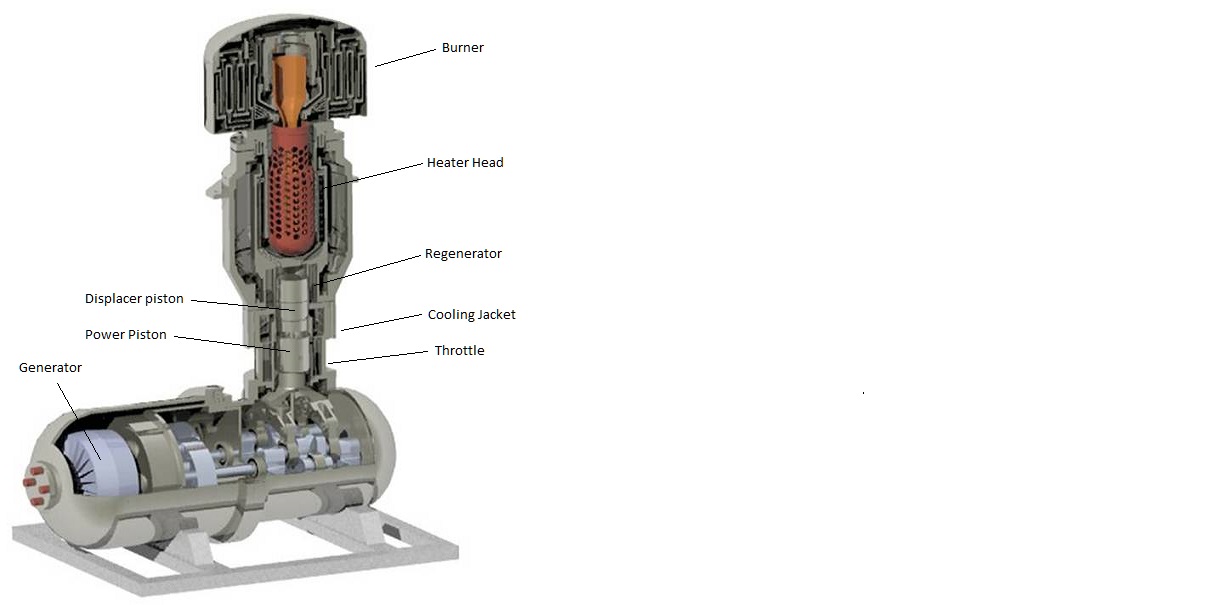
The Dual Shell Stirling Engine consists of 6 modular components:
1. A Burner, to provide a heat source for the engine;
2. a Heater Head (with Dual Shell), to rapidly transfer heat into the engine;
3. a combination Cylinder/Throttle/Cooling Jacket, to house the piston drive mechanism, regulate power draw, and rapidly transfer heat out of the engine
4. a Regenerator, to improve the heat engine efficiency by recycling heat
5. a Drive Mechanism, to extract power from the engine
6. a Generator Assembly, to generate electricity.
ADI Thermals Dual Shell Stirling Engine Generator System.
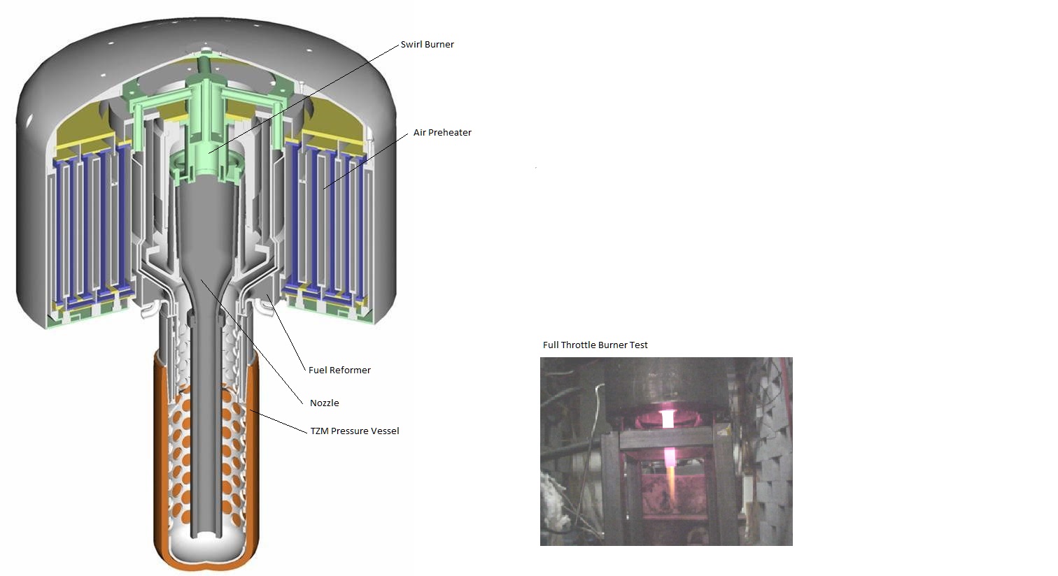
Burner
The function of the burner is to efficiently supply heat to the engine. The burner (see figure below) consists of a central vertical core shaped burner and nozzle surrounded by the successive concentric folds of an air preheater. The function of the air preheater is to use hot exhaust gases to heat incoming air prior to combustion. If this function were omitted, most of the heat contained in the hot exhaust would be wasted. Cool ambient air entering at the outer ring of the air preheater is drawn inward to the burner past hot exhaust gases from the burner, separated from the exhaust by the thin sheets of a folded metal barrier (of large surface area). The cool incoming air is heated to 1700 deg F by the outgoing exhaust gases before entering the central swirl burner. Gaseous fuel is injected at the swirl burner and mixes thoroughly with the air for complete combustion as it travels downwards through the central nozzle. The nozzle then exhausts into a test tube shaped heat exchanger embedded in the heater head. The hot exhaust gases reverse flow and travel up through a forest of heat exchanger nodes supplying heat to the engine heater head. After exiting the heater head at close to 2200 deg F, the exhaust is cooled to 1900 deg F as a small portion of heat feeds a fuel reformer (used to enhance combustion). Most of the remaining heat in the exhaust is then transferred to the incoming air stream in the air preheater. Final exhaust temperatures are only about 300 deg F. After thorough experimental testing and fine tuning of its advanced burner system (which recycles exhaust heat to warm the inlet air), ADI Thermal can achieve burner effiencies of 85%.
ADI Thermals Burner System (incl Air Preheater and Fuel Reformer).
Heater Head
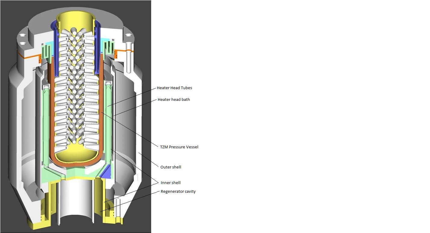
The heater head is a high temperature heat transfer mechanism. The function of the heater head is to reliably and efficiently transfer heat from the burner exhaust into the engine. The heater head is one of the trickiest parts of engine to design, because it must withstand very high temperatures from the burner and very high pressures from the engine. Materials tend to weaken and fail at very high temperatures. This is the reason why all other Stirling engines must operate at temperatures of only 1200 deg F or less. As with all engines, efficiency increases directly with temperature. ADI Thermals engine can operate at temperatures up to 2000 deg F by using its patented Dual Shell Design. The hot end of ADIs engine is contained within a 2nd shell. The hot inner shell contains the heated portion of the engines working gas (which is Helium). The cool outer shell contains the high pressure of the engines working gas. The volume between the two shells is well insulated and the pressure in this volume equalizes to the median engine operating pressure. As a result, the inner shell experiences relatively small pressure fluctuations at high temperature and the cool outer shell contains the engines high pressures (relative to atmospheric).
The heater head consists of a set of helium transfer tubes surrounding the burner cavity within a bath of molten calcium. Each of the heater head tubes represents a small engineering triumph in itself as it is actually 8 tubes consolidated into one, manufactured using a process known as diffusion bonding. The heater head is seperated from the burner cavity by a test tube shaped pressure barrier made of TZM alloy - one of the few substances able to withstand high pressure and high temperature simultaneously. The TZM vessel experiences atmostpheric pressure from the burner cavity inside and average engine pressure from the engine heater head outside. The TZM pressure vessel is relatively small and is an item that can be forged. Burner exhaust gases at 2800 deg F transfer heat through the TZM vessel into the heater head calcium bath which engine dynamics will maintain at 2000 deg F. The heat exits the heater head as the helium flows cyclically through the heater head tubes.
ADI Thermals High Temperature Heater Head.
Cylinder/Throttle/Cooling Jacket
The cylinder with attached engine throttle and cooling jacket lies directly below the heater head. The piston drive mechanism operates inside of the cylinder. The attached cooling jacket surrounds the cylinder, separated from the heater head by a short space which is occupied by the Regenerator. A throttle mechanism, also surrounding the cylinder lies immediately below the cooling jacket. The displacer pistons upward stroke forces the helium working gas to exit the top of the cylinder and travel in sequence through the heater head, regenerator, cooling jacket and back into the lower cylinder. This cools the helium. The displacer piston downstroke reverses the process, forcing helium to flow in the opposite direction and heating the helium. The cyclical function of these processes create the Stirling heat cycle described earlier which drives the engine.
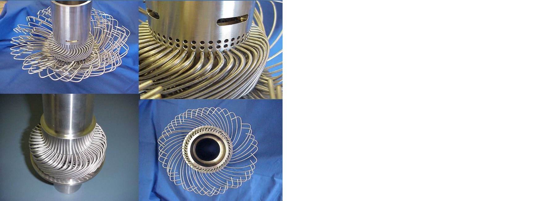
The cooling jacket is composed of an ingeniously designed nest of narrow helium transport tubes - connecting the cylinder to the top face of the cooling jacket and enclosed in a compact water bath chamber. There are 192 tubes of only 4 basic shapes in order to minimize manufacturing cost. All of the tubes are simultaneously vacuum brazed into the cylinder and boundary shells for a perfect hermetic seal. Water at ambient pressure is pumped through the cooling jacket and carries heat away from the cooling tubes.
The throttle is a gear actuated valve that opens to port the cylinder to the crank case. This porting creates a sudden volume increase in the working gas and reduces compression in the cycle. The throttle thus allows the engine to quickly adjust its speed by spoiling the compression.
ADI Thermals Compact Cooling Jacket.
Regenerator
The regenerator occupies the volume outside the cylinder and inside the dual shell, between the heater head and the cooling jacket. It is a simple device with a complex task. The regenerator stores heat as the helium is cooled and recycles that energy by returning heat as the helium is heated. It is basically a porous thermal mass and to function well, it must have excellent heat conduction perpendicular to the helium flow, but poor heat conduction parallel to the flow. Heat moving parallel to the helium flow is wasted heat that performs no work and represents inefficiency. A regenerator must not restrict the flow to any significant degree. ADI Thermal uses a well tested wire mesh regenerator with a precise uniform porosity encased in a cylindrical cartridge for quick easy assembly.
Drive Mechanism
The drive mechanism consists of two reciprocating pistons (power and displacer), both residing in the same cylinder. The displacer piston oscillates at the top of the cylinder and the power piston oscillates at the bottom of the cylinder. They are connected to a common crank at different angles such that their sinusoidal oscillations are 90 degrees out of phase. The crank arms are designed to ensure close proximity with zero interference. A near frictionless coating developed at Argonne Labs is used on the reciprocating parts to minimize friction losses. The crank case, directly below the cyinder, utilizes dual counter rotating cranks to eliminate vibration. This drive configuration is known as a rhombic drive. In reciprocating engines, the oscillating pistons introduce a shaking to the engine. Counterweights can be attached to the crank to counterbalance the piston motion, but those same counterweights will then cause lateral vibration. If you have enough pistons, there are some creative solutions, but few of them are perfect. With only two pistons, the best solution is to have two synchronized counter rotating cranks. Then the counter weights in each crank that balance the piston weights counterbalance each other when they swing in the lateral directions. The net result is no vibration in steady state operation.
On the generator side of the crank case, the crankshafts pass through a gear box to ensure synchronous motion and fly wheels are used to ensure steady torque output for a clean output signal. Spiral gears are used to minimize noise.
Drive Mechanism
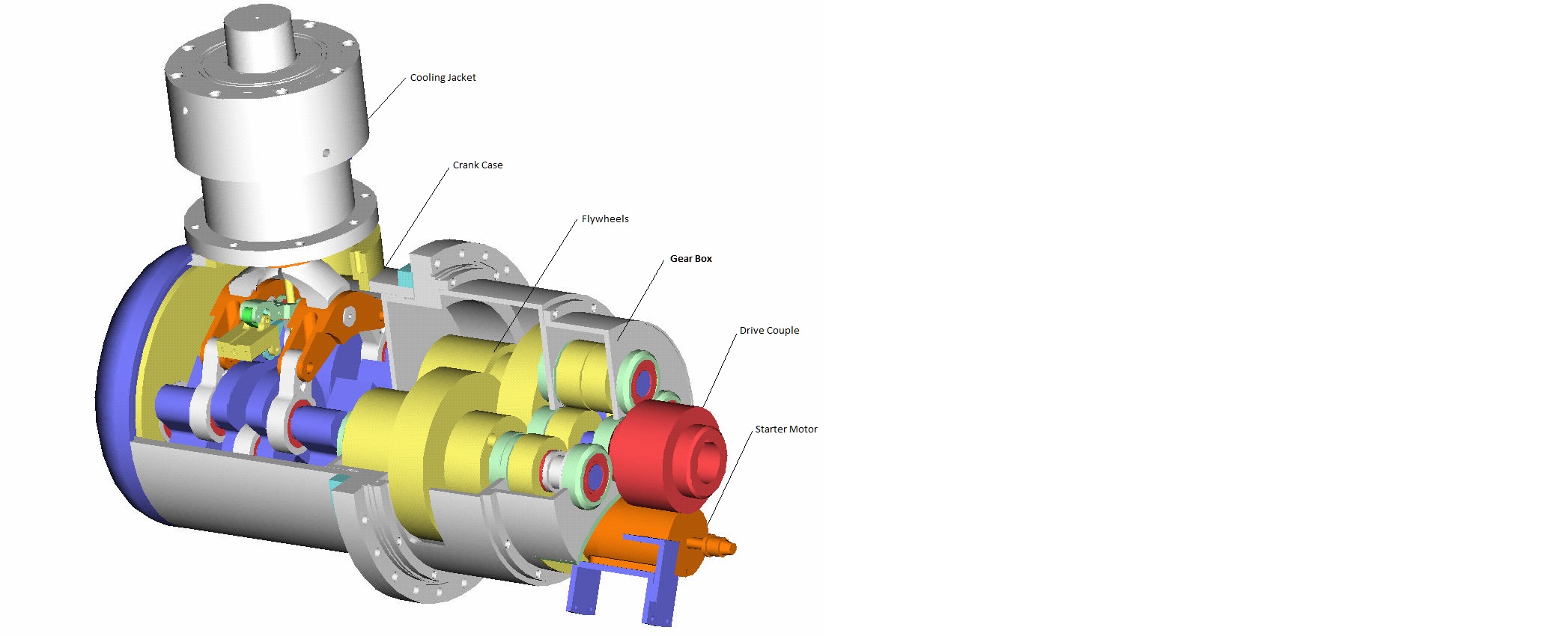
Generator Assembly
The Generator is housed within a generator case which abuts the crank case. It houses a Marathon 25 KW 3-phase Generator coupled to the engine crank case with spline type drive couple. A starter motor is also enclosed for use in the initial start up. Eventually it is planned to replace the tried and true Marathon generator with a poly-phase permanent magnet generator with built in rectifier. This will significantly reduce the size of the generator assembly and eliminates the need for flywheels and starter motor. The polyphase generator outputs 24 phase power and uses a rectifier to clean up the output signal to something useful like single phase or 3-phase. The rectifier can also be used to clean up any output irregularities produced by output torque variations. Hence the heavy flywheels can be eliminated. Since permanent magnet generators can become motors when run in reverse, the starter motor can also be eliminated.